By Laura Risley
Ocean data assimilation (DA) is vital. Firstly, it is essential to improving forecasts of ocean variables. Not only that, the interaction between the ocean and atmosphere is key to numerical weather prediction (NWP) as coupled ocean-atmosphere DA schemes are used operationally.
At present, observations of the ocean currents are not assimilated operationally. This is all set to change, as satellites are being proposed to measure these ocean currents directly. Unfortunately, the operational DA systems are not yet equipped to handle these observations due to some of the assumptions made about the velocities. In my work, we propose the use of alternative velocity variables to prepare for these future ocean current measurements. These will reduce the number of assumptions made about the velocities and is expected to improve the NWP forecasts.
What is DA?
DA combines observations and a numerical model to give a best estimate of the state of our system – which we call our analysis. This will lead to a better forecast. To quote my lunchtime seminar ‘Everything is better with DA!’.
Our model state usually comes from a prior estimate which we refer to as the background. A key component of data assimilation is that the errors present in both sets of data are taken into consideration. These uncertainties are represented by covariance matrices.
I am particularly interested in variational data assimilation, which formulates the DA problem into a least squares problem. Within variational data assimilation the analysis is performed with a set of variables that differ from the original model variables, called the control variables. After the analysis is found in this new control space, there is a transformation back to the model space. What is the purpose of this transformation? The control variables are chosen such that they can be assumed approximately uncorrelated, reducing the complexity of the data assimilation problem.
Velocity variables in the ocean
My work is focused on the treatment of the velocities in NEMOVAR. This is the data assimilation software used by the NEMO ocean model, used operationally at the Met Office and ECMWF. In NEMOVAR the velocities are transformed to their unbalanced components, and these are then used as control variables. The unbalanced components of the velocities are highly correlated, therefore contradicting the assumption made about control variables. This would result in suboptimal assimilation of future surface current measurements – therefore we seek alternative velocity control variables.
The alternative velocity control variables we propose for NEMOVAR are unbalanced streamfunction and velocity potential. This would involve transforming the current control variables, the unbalanced velocities, to these alternative variables using Helmholtz Theorem. This splits a velocity field into its nondivergent (streamfunction) and irrotational (velocity potential) parts. These parts have been suggested by Daley (1993) as more suitable control variables than the velocities themselves.
Numerical Implications of alternative variables

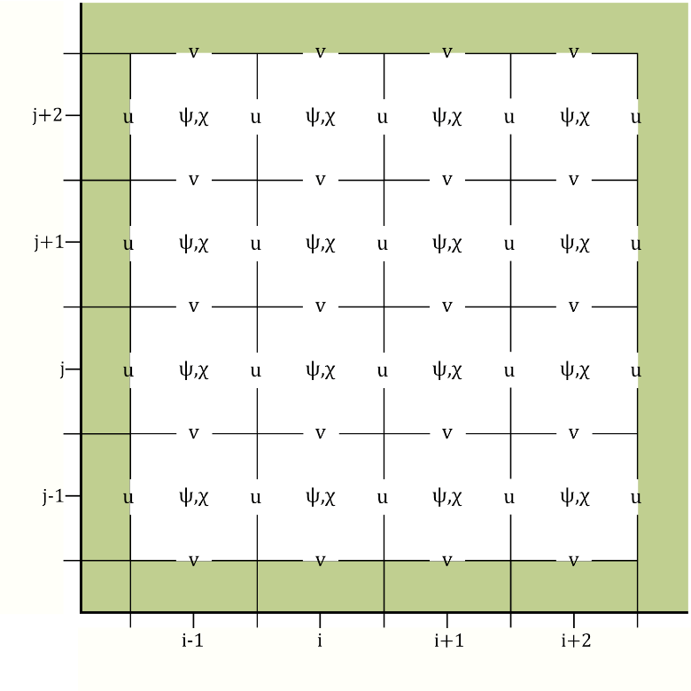
We have performed the transformation to these proposed control variables using the shallow water equations (SWEs) on a 𝛽-plane. To do so we discretised the variables on the Arakawa-C grid. The traditional placement of streamfunction on this grid causes issues with the boundary conditions. Therefore, Li et al. (2006) proposed placing streamfunction in the centre of the grid, as shown in Figure 1. This circumvents the need to impose explicit boundary conditions on streamfunction. However, using this grid configuration leads to numerical issues when transforming from the unbalanced velocities to unbalanced streamfunction and velocity potential. We have analysed these theoretically and here we show some numerical results.
Figure 1: The left figure shows the traditional Arakawa-C configuration (Lynch (1989), Watterson (2001)) whereby streamfunction is in the corner of each grid cell. The right figure shows the Arakawa-C configuration proposed by Li et al. (2006) where streamfunction is in the centre of the grid cell. The green shaded region represents land.
Issue 1: The checkerboard effect
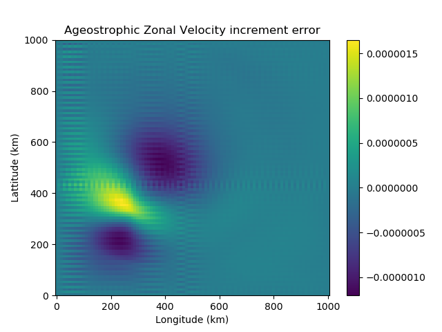
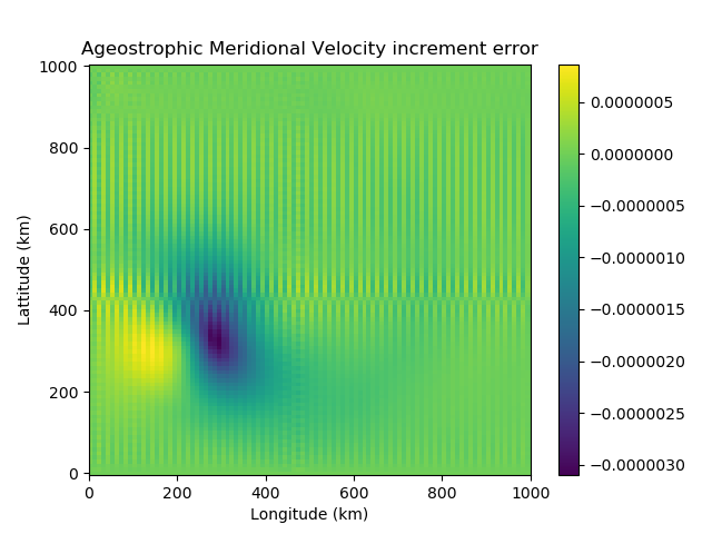
The transformation from the unbalanced velocities to unbalanced streamfunction and velocity potential involves averaging derivatives, due to the location of streamfunction in the grid cell. This process causes a checkerboard effect – whereby we have numerical noise entering the variable fields due to a loss of information. This is clear to see numerically using the SWEs. We use the shallow water model to generate a velocity field. This is transformed to its unbalanced components and then to unbalanced streamfunction and velocity potential. Using Helmholtz Theorem, the unbalanced velocities are reconstructed. Figure 2 shows the checkboard effect clearly in the velocity error.
Figure 2: The difference between the original ageostrophic velocity increments, calculated using the SWEs, and the reconstructed ageostrophic velocity increments. These are reconstructed using Helmholtz Theorem, from the ageostrophic streamfunction and velocity potential increments. On the left we have the zonal velocity increment error and on the right the meridional velocity increment error.
Issue 2: Challenges in satisfying the Helmholtz Theorem
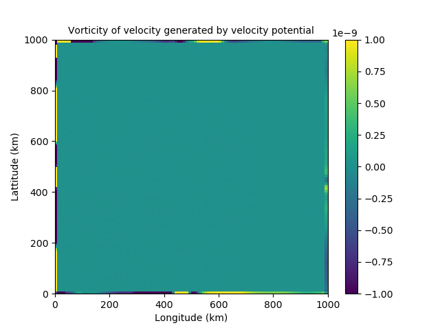
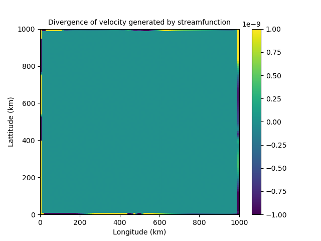
Helmholtz theorem splits the velocity into its nondivergent and irrotational components. We discovered that although streamfunction should be nondivergent and velocity potential should be irrotational, this is not the case at the boundaries, as can be seen in figure 3. This implies the proposed control variables are able to influence each other on the boundary. This would lead to them being strongly coupled and therefore correlated near the boundaries. This directly conflicts the assumption made that our control variables are uncorrelated.
Figure 3: Issues with Helmholtz Theorem near the boundaries. The left shows the divergence of the velocity field generated by streamfunction. The right shows the vorticity of the velocity field generated by velocity potential.
Overall, in my work we propose the use of alternative velocity control variables in NEMOVAR, namely unbalanced streamfunction and velocity potential. The use of these variables however leads to several numerical issues that we have identified and discussed. A paper on this work is in preparation, where we discuss some of the potential solutions. Our next work will further this investigation to a more complex domain and assess our proposed control variables in assimilation experiments.
References:
Daley, R. (1993) Atmospheric data analysis. No. 2. Cambridge university press.
Li, Z., Chao, Y. and McWilliams, J. C. (2006) Computation of the streamfunction and velocity potential for limited and irregular domains. Monthly weather review, 134, 3384–3394.
Lynch, P. (1989) Partitioning the wind in a limited domain. Monthly weather review, 117, 1492–1500.
Watterson, I. (2001) Decomposition of global ocean currents using a simple iterative method. Journal of Atmospheric and Oceanic Technology, 18, 691–703