By Dony Christianto (d.christianto@pgr.reading.ac.uk)
“When do storms really happen?”
It sounds like a simple question—but in the tropics, there is rarely a simple answer.
We often learn this simple process: daytime heating drives peak afternoon rainfall. It is a useful idea—and in many cases, it works. But as we looked more closely at rainfall in Papua, it became clear that the atmosphere was telling a more complex story.
This work began in the field, in southern Papua near Timika. We worked with a network of Automatic Weather Stations (AWS) located across the extraordinary landscape of southern Papua (Figure 1). Across roughly 100 km, the terrain rises from sea level to mountain peaks exceeding 4,700 m. Along this steep transition, particularly in the foothill regions, rainfall reaches some of the highest values in the world, with annual totals of around 12,500 mm.
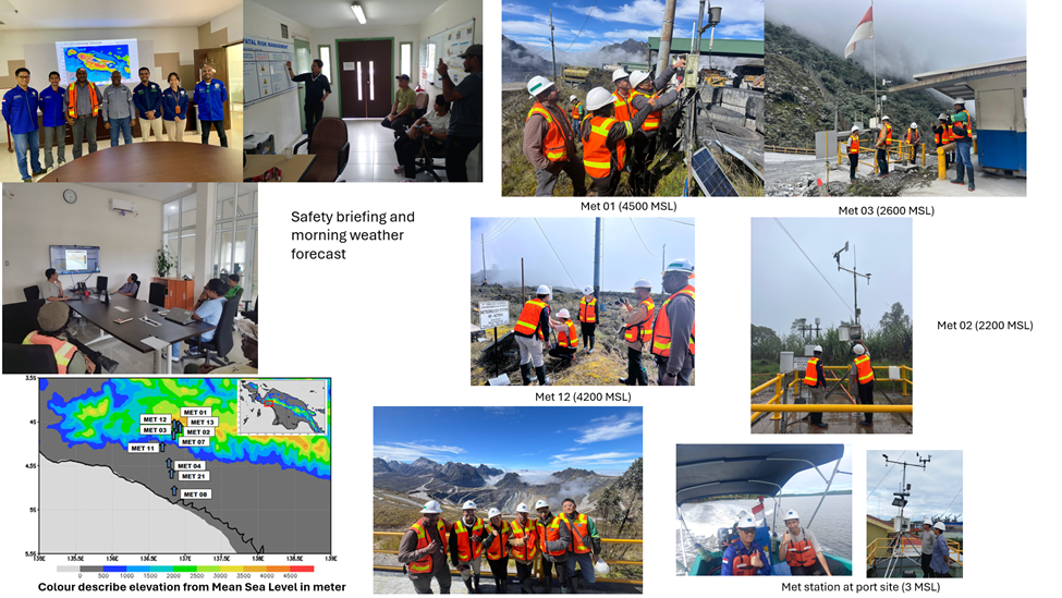
Figure 1: Automatic Weather Station network across Papua, spanning coast to high mountains, providing critical observations in a complex tropical environment.
This combination of coastline, lowland, and steep mountains creates a highly dynamic environment. Papua is not just another tropical region—it is a natural laboratory where local and large-scale atmospheric processes interact in complex ways.
The AWS data used in this study comes from a collaboration between PT Freeport Indonesia and BMKG (the Indonesian Agency for Meteorology, Climatology, and Geophysics). Maintaining these observations requires field visits, safety briefings, and working in remote areas where conditions can change rapidly. It is a reminder that every dataset has a story behind it—and that reliable ground observations remain essential, especially in regions as complex as Papua. This becomes particularly important when we consider how rainfall is commonly studied today.
Satellite products such as GPM-IMERG are widely used because they provide global coverage. In many studies, they are treated as a reference for understanding rainfall behaviour. But before relying on them, it is important to ask: how well do they represent what actually happens at the surface?
To address this, we compared satellite rainfall estimates with AWS observations in Papua (Figure 2).
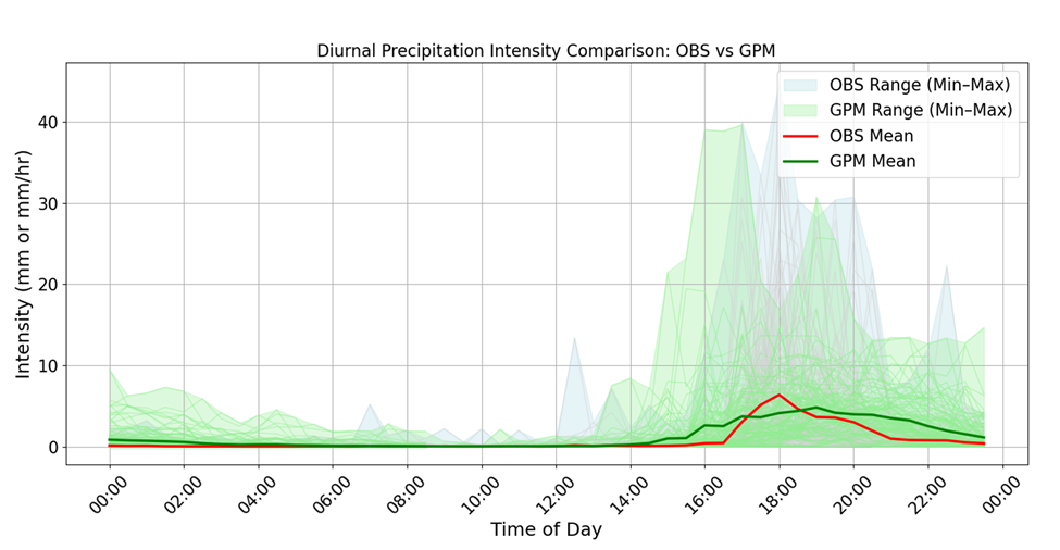
Figure 2: Comparison of diurnal rainfall intensity between ground observations (AWS) and satellite estimates (GPM-IMERG), showing a consistent delay in satellite peak timing, with observed rainfall peaking around 16:00 local time and GPM-IMERG peaking later.
What we found was consistent across the dataset: satellite rainfall peaks tend to occur later than those observed at the ground, typically by around one to three hours. This delay reflects that satellites are more sensitive to mature convective systems and therefore detect rainfall after storms have already developed.
At first glance, a difference of a few hours may not seem significant. However, in meteorology, timing is critical.
Satellite datasets are often used to evaluate weather and climate models. If rainfall timing is systematically shifted, models that appear to perform well against satellite data may not accurately represent real surface processes. This also has implications for applications such as early warning systems, where even small timing differences can influence how rainfall events are detected.
Having established this, we then turned to a more fundamental question: when does rainfall actually occur?
While rainfall in Papua often peaks in the late afternoon (around 15:00–18:00 local time), our analysis revealed a second important rainfall regime in the early morning, typically between 03:00 and 09:00 (Figure 3).
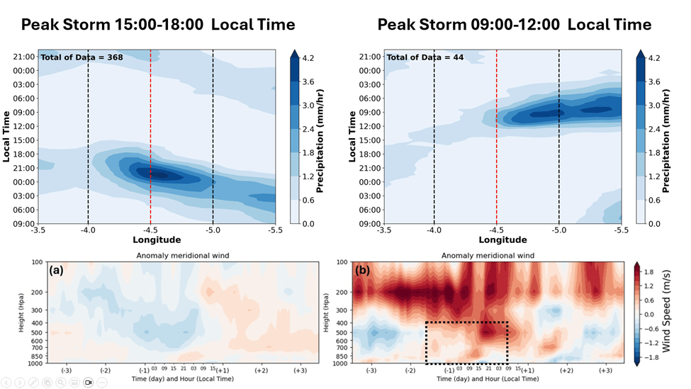
Figure 3: Contrasting rainfall regimes in Papua: afternoon storms (15:00–18:00 LT) are associated with offshore propagation from inland regions, while morning storms (09:00–12:00 LT) are linked to onshore flow bringing precipitation inland. The lower panels show meridional wind anomalies, with blue indicating southward (offshore) flow and red indicating northward (onshore) flow.
These two rainfall peaks are not simply different in timing; they are produced by different atmospheric processes.
Afternoon rainfall is largely driven by local processes. Solar heating during the day warms the land surface, causing air to rise, consequently triggering convection. In Papua, this process is strongly enhanced by the presence of mountains, which help initiate and organise storm development. These systems typically form over land and propagate towards the coast.
Morning rainfall, in contrast, often originates over the ocean. During the night, convective systems develop offshore and are transported inland by low-level winds. In this case, rainfall is not initiated locally but carried from the sea.
This leads to a key insight: rainfall timing is closely linked to wind direction.
When winds are directed offshore (from land towards the sea), they favour afternoon and evening rainfall over land. Conversely, when winds are onshore (from sea towards land), they transport moisture inland and are associated with morning rainfall. These alternating wind regimes create distinct “windows” for storm development throughout the day.
The next question is: what controls these wind patterns? The answer lies in larger-scale atmospheric processes.
Phenomena such as the Madden–Julian Oscillation (MJO), equatorial Rossby waves, and seasonal monsoon circulations influence the background wind environment over Papua. For example, different phases of the MJO are associated with shifts in wind direction and moisture transport. Some phases favour onshore flow, increasing the likelihood of morning rainfall, while others favour conditions more conducive to afternoon convection.
This highlights an important point: rainfall in Papua is not controlled by a single mechanism, but by interactions across multiple scales.
This is where the role of local characteristics becomes critical.
Every region has its own unique combination of topography, coastline, and atmospheric conditions. These factors shape local circulation patterns, which determine how that region responds to larger-scale climate phenomena. This is particularly important in the tropical Maritime Continent, where thousands of islands differ in size, shape, elevation, and land–sea distribution. These differences influence surface properties such as albedo, heat capacity, and moisture availability, which in turn affect how energy is distributed within the atmosphere.
As a result, each island develops its own local circulation system. Even under the same large-scale forcing—such as the MJO or monsoon—different regions can exhibit very different rainfall behaviour. The interaction between local geography and atmospheric processes creates a wide range of responses across the region.
Papua, with its steep topography and strong land–sea contrasts, provides a clear example of this complexity.
From field observations to large-scale atmospheric dynamics, this study highlights a simple but important message: understanding rainfall in the tropics requires considering both the local environment and the broader climate system.
Because in regions like Papua, rainfall is determined not by a single process, but by the interaction of many.


